OFFICIAL PINOUT DIAGRAM: BOSCH EDC17CV45.png (Platform / Bench)625,200 bytes
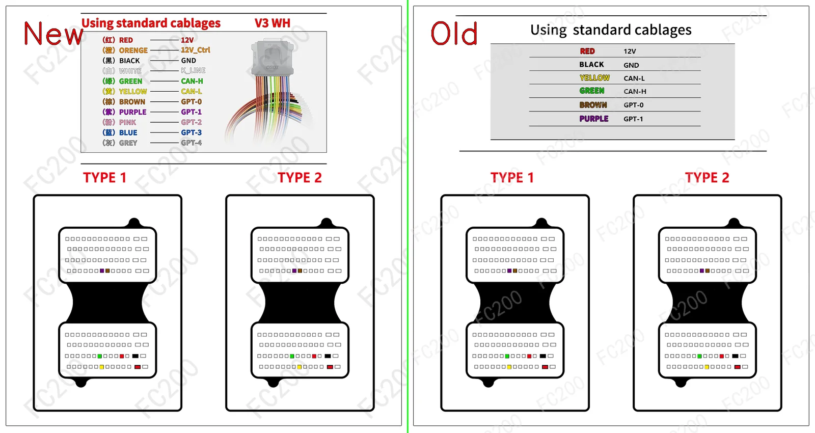
STEP-BY-STEP BENCH CONNECTION PROCEDURE (HOWTO PROTOCOL)BENCH / BOOT
- Step 1 (Terminal 30 & Terminal 15 Power): Apply regulated bench power
13.5V — 13.8Vto constant battery (T30), switched ignition (T15), and ground (GND) pins according to the harness color code above. - Step 2 (CAN Bus & GPT0 / GPT1 Signals): Connect
CAN-H&CAN-L, along with signal leadsGPT0 (S1)&GPT1 (S2)to enter bench service mode without opening the ECU housing. - Step 3 (Full PFLASH + DFLASH Backup Read): Before writing any calibration, read and archive a full backup of internal Program Flash (
PFLASH) and Data Flash / EEPROM (DFLASH).
VEHICLES EQUIPPED WITH ECU EDC17CV45 (2)VEHICLE COMPATIBILITY
| Make | Model & Engine | ECU & MCU | Action |
|---|---|---|---|
| Manitou | Series 30 T (MSI 30 V24703-M-EU32 50) | BOSCH EDC17CV45 (TC1782) |
Open Vehicle → |
| Manitou | All Brand Models (Direct ECU Label Lookup) (Read/Write EEPROM/FLASH, CheckSum) | BOSCH EDC17CV45 (TC1766) |
Open Vehicle → |